Measuring the Forward Voltage Drop of LEDs
· hardware
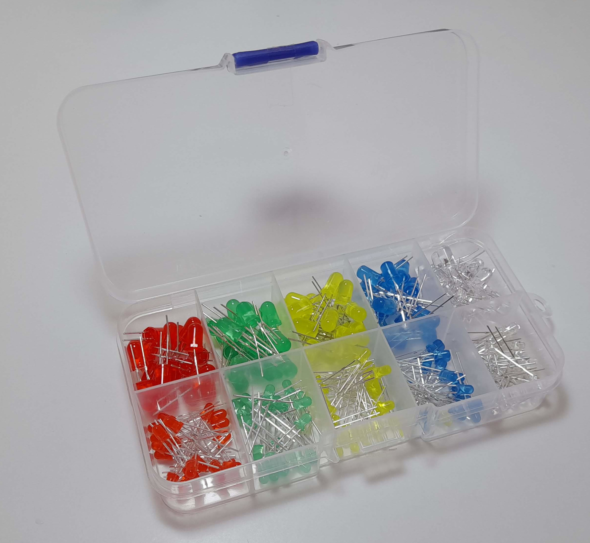
A package with a bunch of electronic components just arrived! I was curious if I could measure the forward voltage drop of the various colors of LEDs, so that I could choose a suitable current-limiting resistor without looking it up online.
To prevent me from burning up the LEDs, I set up a 1 kΩ resistor in series, as a current-limiting resistor. When applying 5V from a USB power supply, the resistor will limit the current of the circuit to a maximum of 5 mA, which should be safe enough and not burn any LEDs.
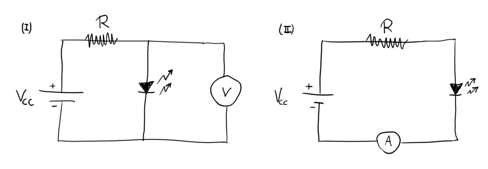
For probing the forward voltage drop of each LED, it suffices to measure the voltage across the leads, as shown below on the circuit (i). For probing the current through the LED, the circuit must be rearranged and the multimeter put in series, as show below below on the configuration (ii) .
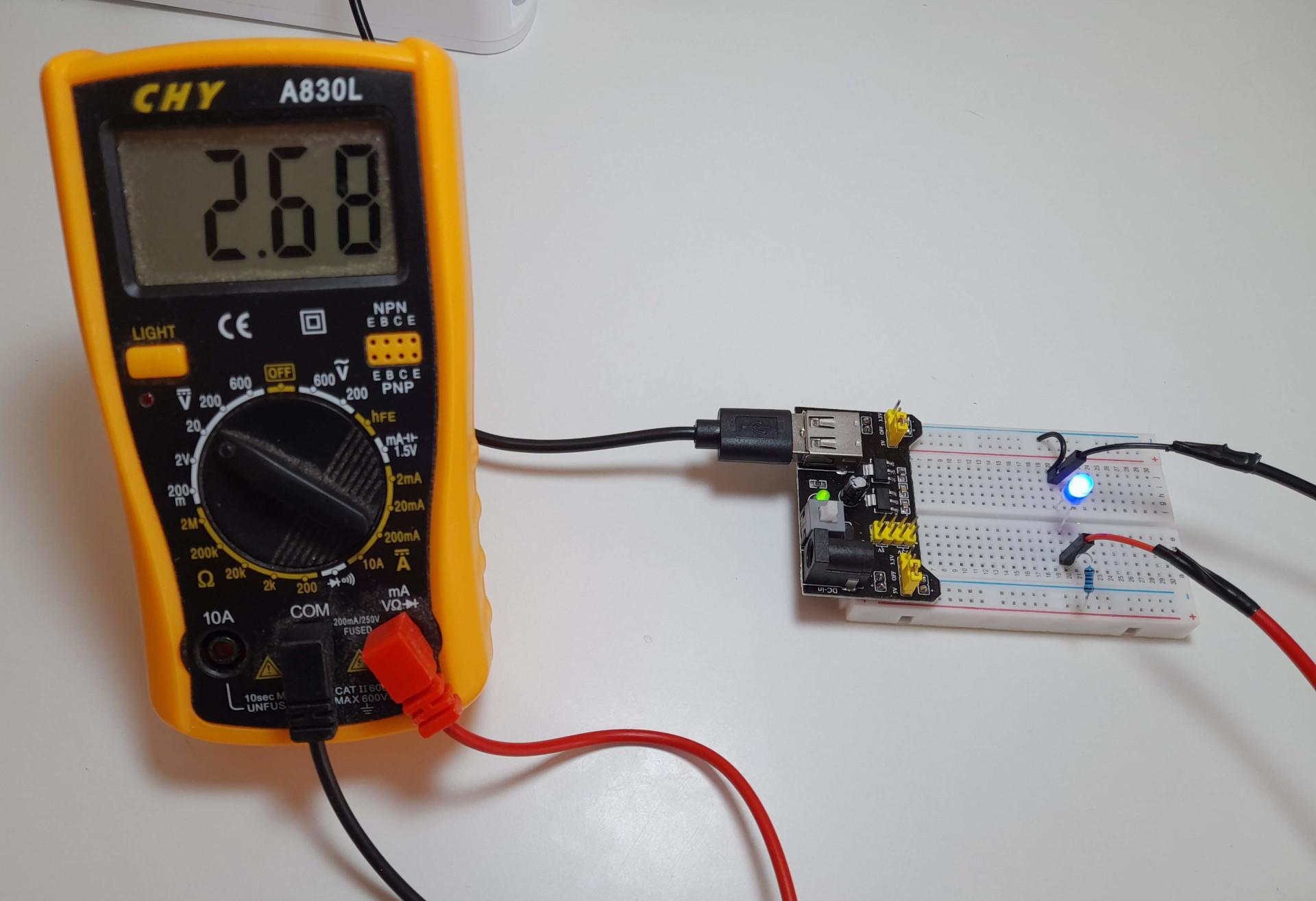
This is what the setup looked like when measuring the forward voltage drop:
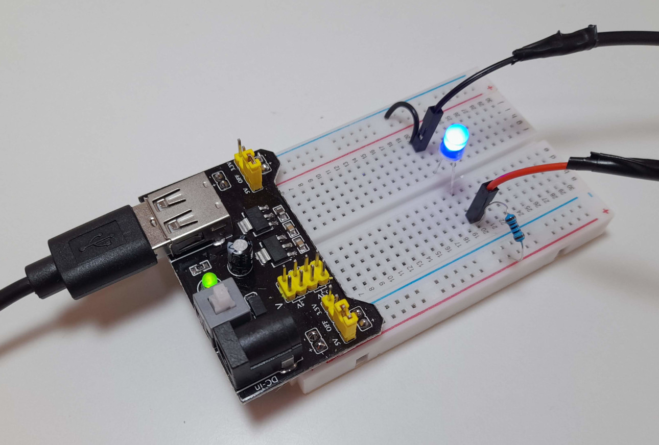
And here's a closer look at the circuit itself:
Finally, here are the results I've got:
Supply: 5.22 V
I_max:  5.23 mA
R:       998 Ω

LED            V_drop   I_led
-------------------------------
Big Red        1.90 V   3.30 mA
Small Red      1.89 V   3.31 mA
Big Green      1.94 V   3.26 mA
Small Green    1.92 V   3.28 mA
Big Yellow     1.92 V   3.28 mA
Small Yellow   1.89 V   3.31 mA
Big Blue       2.68 V   2.51 mA
Small Blue     2.68 V   2.51 mA
Big White      2.70 V   2.49 mA
Small White    2.72 V   2.49 mA
In the interest of time, I measured a single LED from each category, but I assume the remaining ones will fall into a similar range (within their own color categories).
The small (3 mm diameter) and big (5 mm diameter) variants behaved in an equivalent manner, indicating that the package size has no consequences to the electrical behavior of the component.
While all the LEDs did turn on under the described conditions, the blue and white LEDs were the brighter, while the red, green and yellow LEDs were dimmer, so maybe choice of the resistance of the current-limiting resistor was conservative. For those LEDs colors, a lower value resistor may be employed if one desires to make them light up a bit brighter.